Custom Rotomolded Fuel Tank: Mold, First-Off Parts and Production | Boright
Aluminum cavity tooling, a ribbed polyethylene fuel tank for off-highway equipment, first-off samples and series production — built in-house at Boright Industries, Ningbo, China.
Custom Rotomolded Fuel Tank: Tooling, First-Off Parts and Production
A saddle-shaped polyethylene fuel tank for off-highway equipment. The cavity was built in-house, the first-off parts were moulded on our own machines, and the project moved straight into series production in Ningbo, China.
The tank had to sit over an existing machine frame, hold fuel, and take vibration and rough handling in the field. The customer supplied 3D data and a packaging envelope; the open questions were structural rather than cosmetic: how the ribs should run so the walls stay stiff without adding weight, where the wall thickness would end up on a part this size, where the mounting inserts could sit, and how the filler, vent and drain should be placed so the tank fills and empties cleanly at the angles the machine actually works at.
We worked through those points with the customer before cutting metal, because on a rotomolded part they are all decided by the cavity, not by the moulding cycle.
The mold
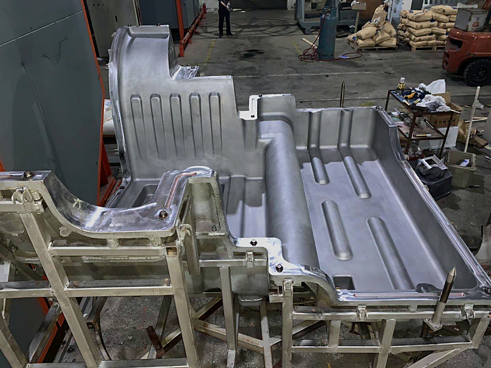
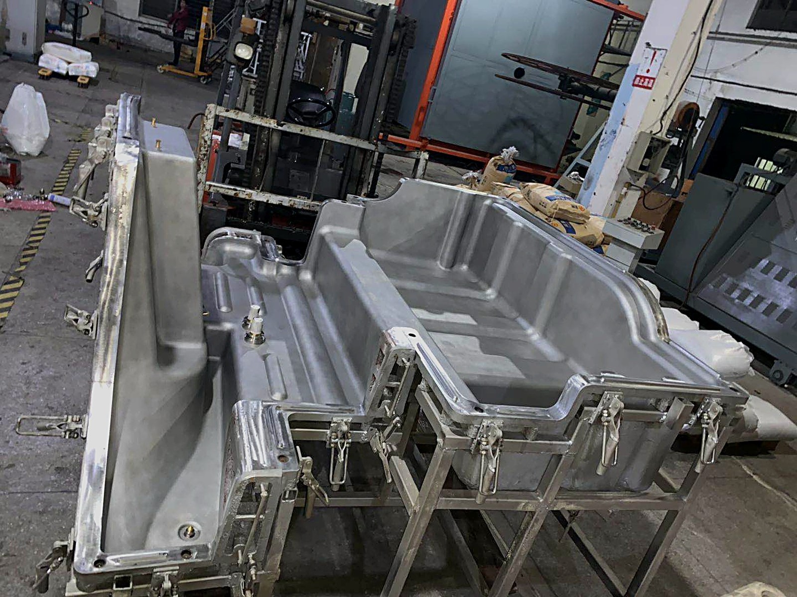
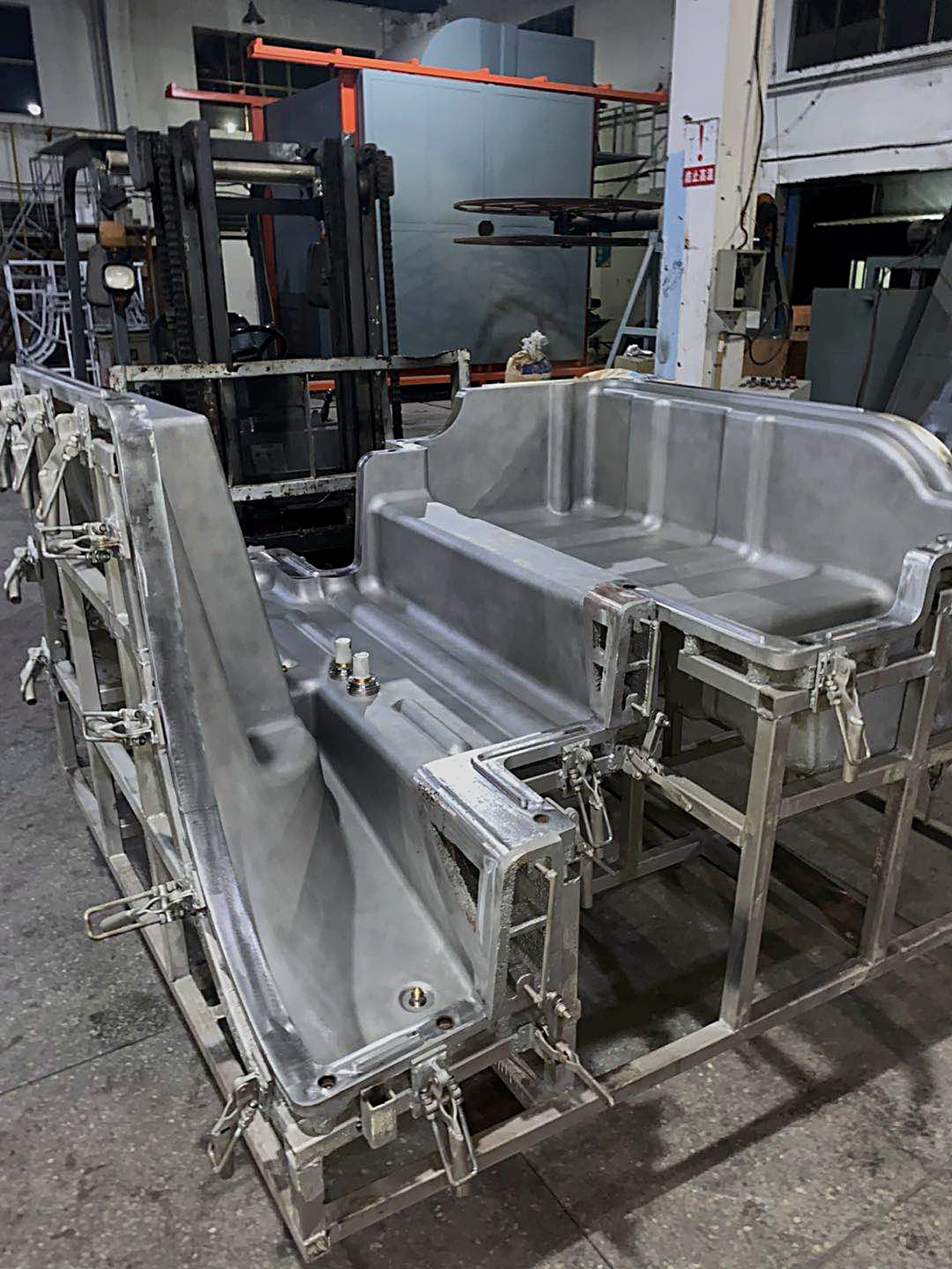
Cavity half after machining — aluminium shell on a steel frameSecond half, closed with toggle clamps; lifting eyes on the frameCavity detail: rib channels, recesses and insert pockets
The tool is two machined aluminium cavity halves carried on welded steel frames and closed with toggle clamps. The rib channels in the cavity become the stiffening ribs on the finished tank; the pockets form the pads where the mounting inserts sit; the raised bosses cut the filler neck, vent and sender flange. Because the tank is a saddle, the two halves are not symmetrical, and the parting line has to follow the machine frame it sits on.
Tooling like this is developed in-house as part of the product, not bought from a catalogue. Mold capability is a supporting function of our rotomolding business — it exists so that custom parts can actually be produced — rather than a standalone mold-making business.
The first-off parts
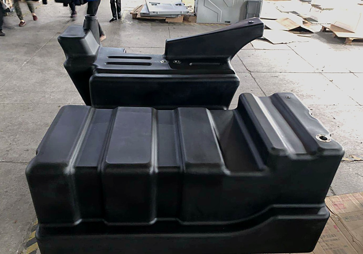
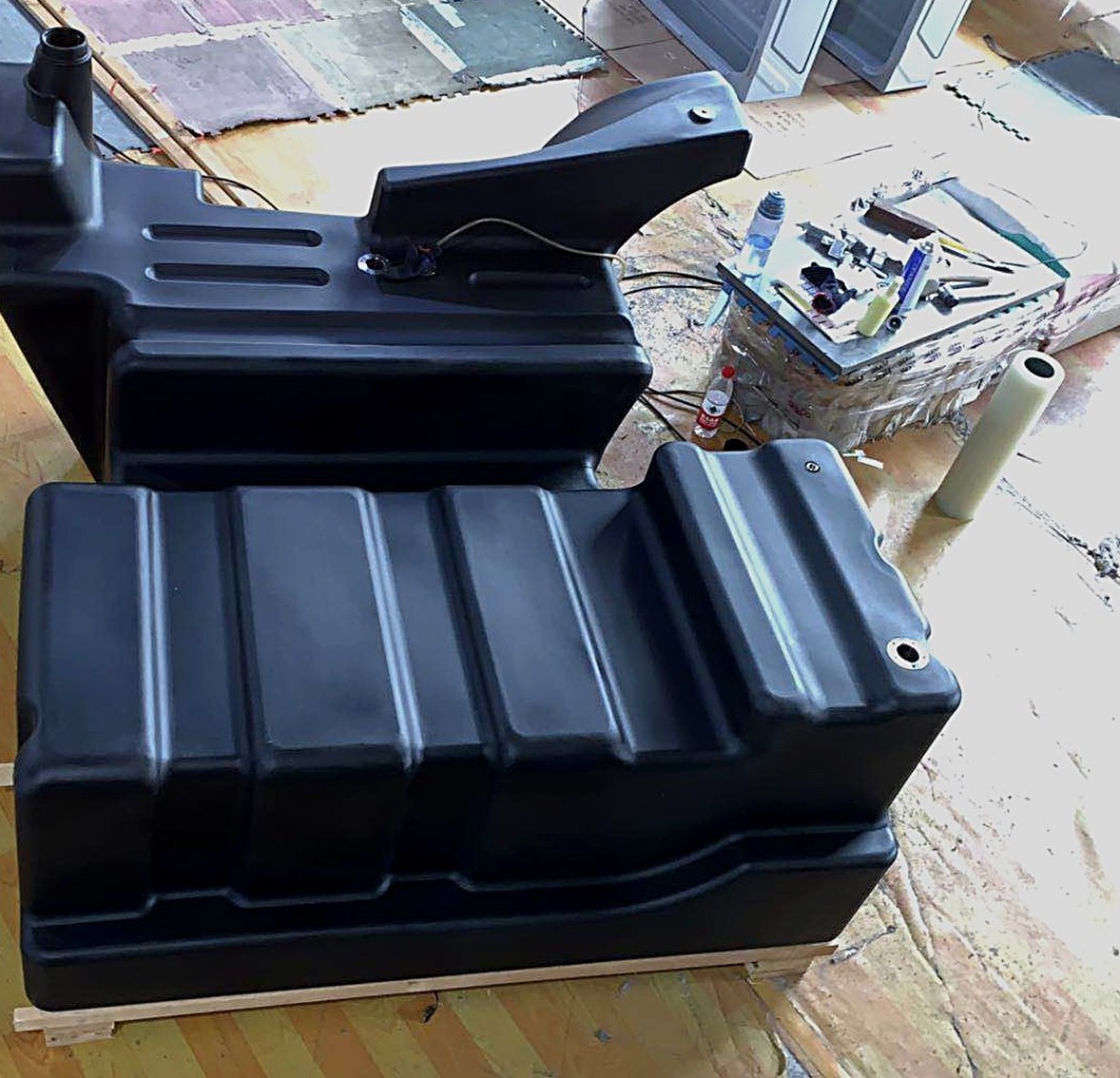
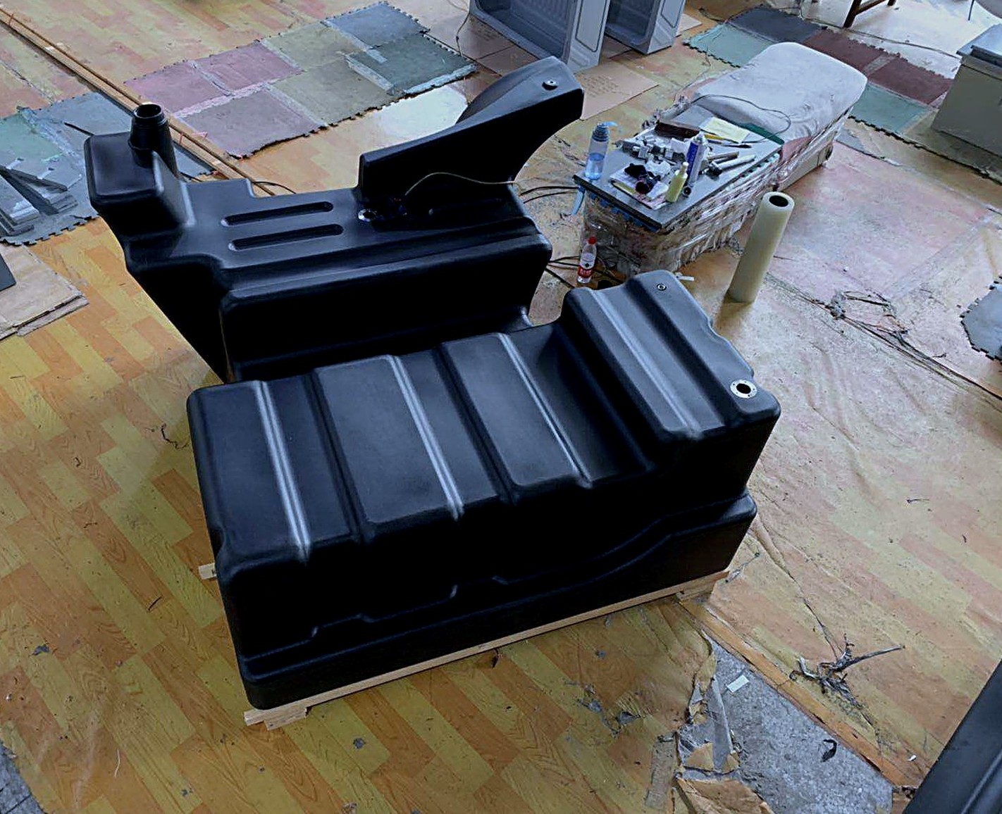
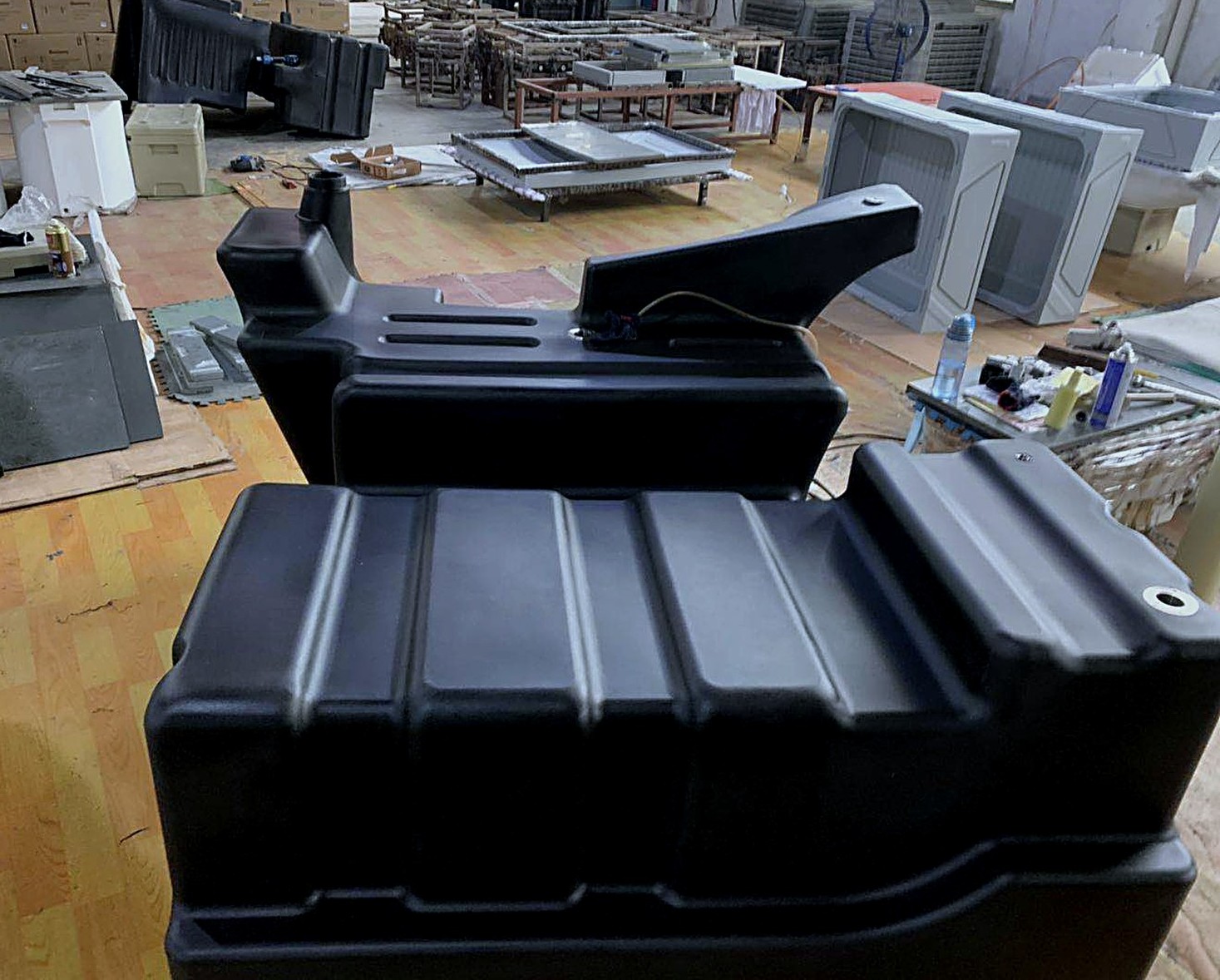
First-off tank, front view — ribbed base and mounting padsRear face: filler neck, vent bosses, sender flange and drainFinished part on the pallet, before packingSide profile in the plant — wall ribs and stepped base
The moulded part carries the whole fuel system interface in one shot: the filler neck and vent bosses on top, the sender flange on the rear face, a drain at the low point, and metal inserts set into the mounting pads so the tank can be bolted to the frame without crushing the wall. The ribs run across the base and up the long walls, which is what keeps a tank this size from oil-canning under load.
What we check on a tank like this
Wall thickness at the ribs, corners and the sender flange — measured on the first-off part, not only on the drawing.
Flatness of the sender flange and the filler neck, so the gaskets seat.
Insert pull-out on the mounting pads.
Filler, vent and drain bore clearance, and that the tank drains fully at working angles.
Leak check on the finished tank before packing.
Where it was made
10+ yearsRotomolding experience
3 machinesShuttle-type, dual station
6–7 moldsPer machine
Up to 20 partsPer mold, 24 h two-shift day
100,000 / yearCooler boxes, annual capacity
1 PU lineHigh-pressure foaming machine
Capacity figures describe the plant as a whole, not this single project. Foaming applies to insulated products; this fuel tank is a single-wall PE part.
Questions buyers ask about this kind of project
Can Boright build the mold as well as the part?
Yes. For custom projects we develop the tooling in-house alongside the product, which is how dimensional and demoulding problems get caught before the first sample. Mold work supports our rotomolding production; it is not a separate mold-making business.
Can you mould a tank or housing from our 3D data?
Send STEP or IGES files, or drawings with the key dimensions and the space the part has to fit. We review draft angles, wall thickness, rib layout, insert placement and demoulding, then quote tooling and part price together.
What is your production capacity?
Three shuttle-type dual-station rotomolding machines, each taking 6–7 molds, with up to 20 parts per mold in a 24-hour two-shift day. Annual capacity is up to 100,000 cooler boxes, and the same lines run tanks, tubs and tool boxes.
Which markets do you ship to?
Products made at our Ningbo plant are exported to the United States, Japan, Korea, Australia, New Zealand and Canada, mainly for brand owners, importers and distributors.
Have a tank, housing or tub that needs tooling?Send the 3D data and the space it has to fit. We will come back with the structural points that matter and a tooling-plus-part quote.
 English
 日本語
 Deutsch
 Français
 Español
 Русский
 Português
繁體中文
Italiano
한국어
ไทย
Tiếng Việt
Bahasa Melayu
Polskie
Shqiptare
عربي
Azərbaycan
Gaeilge
Eesti keel
Euskara
беларуская
български
íslenskur
Bosanski
فارسی
Afrikaans
Dansk
Filipino
Suomalainen
ខ្មែរ
ქართული
ગુજરાતી
қазақ
Kreyòl ayisyen
Hausa
Nederlands
Galego
Català
čeština
ಕನ್ನಡ
Hrvatski
Latinus
Latviski
ພາສາລາວ
Lietuvių
Română
Malagasy
Malti
मराठी
മലയാളം
македонски
Maori
Монгол
বাংলা
Hmoob
Zulu
नेपाली
Norsk
ਪੰਜਾਬੀ
Chichewa
Svenska
Српски
Sesotho
සිංහල
Esperanto
Slovenský
Slovenščina
Kiswahili
Türk
اردو
Hայերեն
Igbo
יידיש
नहीं।
Basa Sunda
Basa Jawa
Yoruba
አማርኛ
ଓଡିଆ
Татар
Frysk
Кыргызча
Corsu
Kurdî
Lëtzebuergesch
Kinyarwanda
IsiXhosa saseMzantsi Afrika
پښتو
Samoa
Gàidhlig na h-Alba
Türkmenler
ئۇيغۇرچە
Ōlelo Hawaiʻi
Kiniki
Shona
Bahasa Indonesia
Save
 English
 日本語
 Deutsch
 Français
 Español
 Русский
 Português